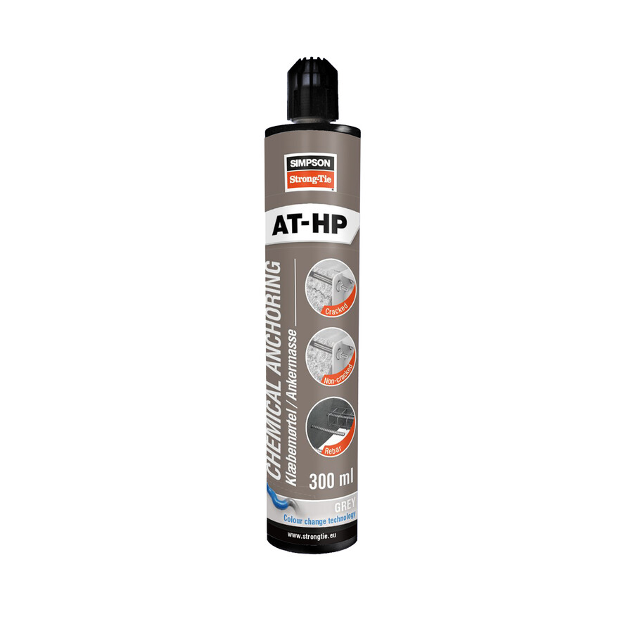
Injektointimassa Meta-akrylaattihartsi
Ankkurointimassa kiinnitettäessä halkeilleeseen betoniin, muuraukseen ja kevytbetoniin.
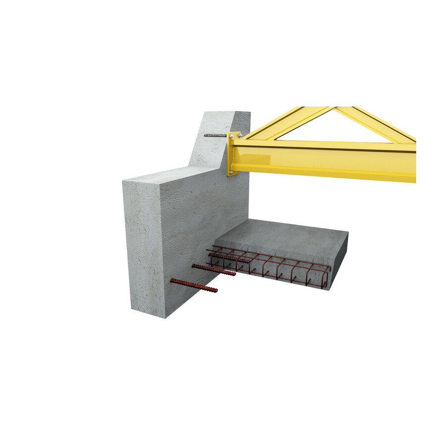
- ETA Option 1 for threaded rod and rebar (for cracked and uncracked concrete)
Tuotteen yksityiskohdat
Ominaisuudet
Materiaali
- Meta-akrylaattihartsi
Hyödyt
- Asennus kosteaan reikään sallittu
- Kiinnittyy kokonaisuudessaan porattuun reikään
- Jännitysvapaa kiinnitys
- Pienemmät reuna- ja keskinäiset etäisyydet
- Raudoitteen liimaaminen ankkuriksi
- Melkein hajuton
Sovellus
Liitos
- Halkeilemattomaan betonin
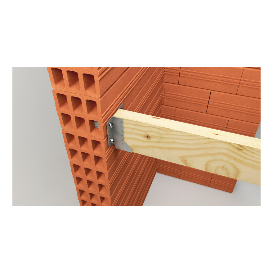
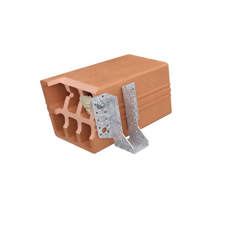
- Muuraukseen
- Kevytbetoniin
Käyttökohteet
- Teräsrakenteet
- Kiskojärjestelmät
- Julkisivut
- Palkit
Tekniset tiedot
Mitat
| Tuotenro | Product information | ||
|---|---|---|---|
| Sisällys [ml] | Weight [kg] | Määrä pakkauksessa [pcs] | |
| ATHP300BG-DK | 300 | 0.575 | 12 |
Design resistance – Tension – NRd [kN] – hef = 8d – Carbon steel 5.8
| Tuotenro | Design resistance – hef = 8d – Carbon steel 5.8 | |||||||
|---|---|---|---|---|---|---|---|---|
| Tension - NRd [kN] | ||||||||
| Halkeillut betoni | Halkeilematon betoni | |||||||
| C20/25 | C30/37 | C40/50 | C50/60 | C20/25 | C30/37 | C40/50 | C50/60 | |
| AT-HP + LMAS M8 | - | - | - | - | 10.7 | 12 | 12 | 12 |
| AT-HP + LMAS M10 | - | - | - | - | 15.9 | 17.8 | 19.3 | 19.3 |
| AT-HP + LMAS M12 | 8.4 | 8.8 | 9 | 9.2 | 21.7 | 24.3 | 26.7 | 28 |
| AT-HP + LMAS M16 | 15 | 15.6 | 16.1 | 16.4 | 34.3 | 38.4 | 42.2 | 44.6 |
| AT-HP + LMAS M20 | - | - | - | - | 50.2 | 56.3 | 61.8 | 65.3 |
| AT-HP + LMAS M24 | - | - | - | - | 67.5 | 75.6 | 83.1 | 87.8 |
Concrete :
1. The design loads have been calculated using the partial safety factors for resistances stated in ETA-approval(s). The loading figures are valid for unreinforced concrete and reinforced concrete with a rebar spacing s ≥ 15 cm (any diameter) or with a rebar spacing s ≥ 10 cm, if the rebar diameter is 10mm or smaller.
2. The figures for shear are based on a single anchor without influence of concrete edges. For anchorages close to edges (c ≤ max [10 hef; 60d]) the concrete edge failure shall be checked per ETAG 001, Annex C, design method A.
3. Concrete is considered non-cracked when the tensile stress within the concrete is\sigmaL +\sigmaR ≤ 0. In the absence of detailed verification\sigmaR = 3 N/mm² can be assumed (\sigmaL equals the tensile stress within the concrete induced by external loads, anchors loads included).
Design resistance – Tension – NRd [kN] – hef = 12d – Carbon steel 5.8
| Tuotenro | Design resistance – hef = 12d – Carbon steel 5.8 | |||||||
|---|---|---|---|---|---|---|---|---|
| Tension - NRd [kN] | ||||||||
| Cracked concrete | Non-cracked concrete | |||||||
| C20/25 | C30/37 | C40/50 | C50/60 | C20/25 | C30/37 | C40/50 | C50/60 | |
| AT-HP + LMAS M8 | - | - | - | - | 12 | 12 | 12 | 12 |
| AT-HP + LMAS M10 | - | - | - | - | 19.3 | 19.3 | 19.3 | 19.3 |
| AT-HP + LMAS M12 | 12.7 | 13.2 | 13.5 | 13.8 | 28 | 28 | 28 | 28 |
| AT-HP + LMAS M16 | 22.5 | 23.4 | 24.1 | 24.5 | 51.4 | 52.7 | 52.7 | 52.7 |
| AT-HP + LMAS M20 | - | - | - | - | 75.4 | 82 | 82 | 82 |
| AT-HP + LMAS M24 | - | - | - | - | 101.3 | 113.4 | 118 | 118 |
Concrete :
1. The design loads have been calculated using the partial safety factors for resistances stated in ETA-approval(s). The loading figures are valid for unreinforced concrete and reinforced concrete with a rebar spacing s ≥ 15 cm (any diameter) or with a rebar spacing s ≥ 10 cm, if the rebar diameter is 10mm or smaller.
2. The figures for shear are based on a single anchor without influence of concrete edges. For anchorages close to edges (c ≤ max [10 hef; 60d]) the concrete edge failure shall be checked per ETAG 001, Annex C, design method A.
3. Concrete is considered non-cracked when the tensile stress within the concrete is\sigmaL +\sigmaR ≤ 0. In the absence of detailed verification\sigmaR = 3 N/mm² can be assumed (\sigmaL equals the tensile stress within the concrete induced by external loads, anchors loads included).
Design resistance – Tension – NRd [kN] – hef = 8d – Stainless steel A4-70
| Tuotenro | Design resistance – hef = 8d – Stainless steel A4-70 | |||||||
|---|---|---|---|---|---|---|---|---|
| Tension - NRd [kN] | ||||||||
| Cracked concrete | Non-cracked concrete | |||||||
| C20/25 | C30/37 | C40/50 | C50/60 | C20/25 | C30/37 | C40/50 | C50/60 | |
| AT-HP + LMAS M8 | - | - | - | - | 10.7 | 12 | 13.2 | 13.9 |
| AT-HP + LMAS M10 | - | - | - | - | 15.9 | 17.8 | 19.6 | 20.7 |
| AT-HP + LMAS M12 | 8.4 | 8.8 | 9 | 9.2 | 21.7 | 24.3 | 26.7 | 28.2 |
| AT-HP + LMAS M16 | 15 | 15.6 | 16.1 | 16.4 | 34.3 | 38.4 | 42.2 | 44.6 |
| AT-HP + LMAS M20 | - | - | - | - | 50.2 | 56.3 | 61.8 | 65.3 |
| AT-HP + LMAS M24 | - | - | - | - | 67.5 | 75.6 | 83.1 | 87.8 |
Concrete :
1. The design loads have been calculated using the partial safety factors for resistances stated in ETA-approval(s). The loading figures are valid for unreinforced concrete and reinforced concrete with a rebar spacing s ≥ 15 cm (any diameter) or with a rebar spacing s ≥ 10 cm, if the rebar diameter is 10mm or smaller.
2. The figures for shear are based on a single anchor without influence of concrete edges. For anchorages close to edges (c ≤ max [10 hef; 60d]) the concrete edge failure shall be checked per ETAG 001, Annex C, design method A.
3. Concrete is considered non-cracked when the tensile stress within the concrete is\sigmaL +\sigmaR ≤ 0. In the absence of detailed verification\sigmaR = 3 N/mm² can be assumed (\sigmaL equals the tensile stress within the concrete induced by external loads, anchors loads included).
Design resistance – Tension – NRd [kN] – hef = 12d – Stainless steel A4-70
| Tuotenro | Design resistance – hef = 12d – Stainless steel A4-70 | |||||||
|---|---|---|---|---|---|---|---|---|
| Tension - NRd [kN] | ||||||||
| Cracked concrete | Non-cracked concrete | |||||||
| C20/25 | C30/37 | C40/50 | C50/60 | C20/25 | C30/37 | C40/50 | C50/60 | |
| AT-HP + LMAS M8 | - | - | - | - | 13.9 | 13.9 | 13.9 | 13.9 |
| AT-HP + LMAS M10 | - | - | - | - | 21.9 | 21.9 | 21.9 | 21.9 |
| AT-HP + LMAS M12 | 12.7 | 13.2 | 13.5 | 13.8 | 31.6 | 31.6 | 31.6 | 31.6 |
| AT-HP + LMAS M16 | 22.5 | 23.4 | 24.1 | 24.5 | 51.4 | 57.6 | 58.8 | 58.8 |
| AT-HP + LMAS M20 | - | - | - | - | 75.4 | 84.4 | 92 | 92 |
| AT-HP + LMAS M24 | - | - | - | - | 101.3 | 113.4 | 124.6 | 131.7 |
Concrete :
1. The design loads have been calculated using the partial safety factors for resistances stated in ETA-approval(s). The loading figures are valid for unreinforced concrete and reinforced concrete with a rebar spacing s ≥ 15 cm (any diameter) or with a rebar spacing s ≥ 10 cm, if the rebar diameter is 10mm or smaller.
2. The figures for shear are based on a single anchor without influence of concrete edges. For anchorages close to edges (c ≤ max [10 hef; 60d]) the concrete edge failure shall be checked per ETAG 001, Annex C, design method A.
3. Concrete is considered non-cracked when the tensile stress within the concrete is\sigmaL +\sigmaR ≤ 0. In the absence of detailed verification\sigmaR = 3 N/mm² can be assumed (\sigmaL equals the tensile stress within the concrete induced by external loads, anchors loads included).
Design resistance – Shear – VRd [kN] – hef = 8d – Carbon steel 5.8
| Tuotenro | Design resistance – hef = 8d – Carbon steel 5.8 | |||||||
|---|---|---|---|---|---|---|---|---|
| Shear - VRd [kN] | ||||||||
| Cracked concrete | Non-cracked concrete | |||||||
| C20/25 | C30/37 | C40/50 | C50/60 | C20/25 | C30/37 | C40/50 | C50/60 | |
| AT-HP + LMAS M8 | - | - | - | - | 7.2 | 7.2 | 7.2 | 7.2 |
| AT-HP + LMAS M10 | - | - | - | - | 12 | 12 | 12 | 12 |
| AT-HP + LMAS M12 | 16.8 | 16.8 | 16.8 | 16.8 | 16.8 | 16.8 | 16.8 | 16.8 |
| AT-HP + LMAS M16 | 30 | 31.2 | 31.2 | 31.2 | 31.2 | 31.2 | 31.2 | 31.2 |
| AT-HP + LMAS M20 | - | - | - | - | 48.8 | 48.8 | 48.8 | 48.8 |
| AT-HP + LMAS M24 | - | - | - | - | 70.4 | 70.4 | 70.4 | 70.4 |
Concrete :
1. The design loads have been calculated using the partial safety factors for resistances stated in ETA-approval(s). The loading figures are valid for unreinforced concrete and reinforced concrete with a rebar spacing s ≥ 15 cm (any diameter) or with a rebar spacing s ≥ 10 cm, if the rebar diameter is 10mm or smaller.
2. The figures for shear are based on a single anchor without influence of concrete edges. For anchorages close to edges (c ≤ max [10 hef; 60d]) the concrete edge failure shall be checked per ETAG 001, Annex C, design method A.
3. Concrete is considered non-cracked when the tensile stress within the concrete is\sigmaL +\sigmaR ≤ 0. In the absence of detailed verification\sigmaR = 3 N/mm² can be assumed (\sigmaL equals the tensile stress within the concrete induced by external loads, anchors loads included).
Design resistance – Shear – VRd [kN] – hef = 12d – Carbon steel 5.8
| Tuotenro | Design resistance – hef = 12d – Carbon steel 5.8 | |||||||
|---|---|---|---|---|---|---|---|---|
| Shear - VRd [kN] | ||||||||
| Cracked concrete | Non-cracked concrete | |||||||
| C20/25 | C30/37 | C40/50 | C50/60 | C20/25 | C30/37 | C40/50 | C50/60 | |
| AT-HP + LMAS M8 | - | - | - | - | 7.2 | 7.2 | 7.2 | 7.2 |
| AT-HP + LMAS M10 | - | - | - | - | 12 | 12 | 12 | 12 |
| AT-HP + LMAS M12 | 16.8 | 16.8 | 16.8 | 16.8 | 16.8 | 16.8 | 16.8 | 16.8 |
| AT-HP + LMAS M16 | 31.2 | 31.2 | 31.2 | 31.2 | 31.2 | 31.2 | 31.2 | 31.2 |
| AT-HP + LMAS M20 | - | - | - | - | 48.8 | 48.8 | 48.8 | 48.8 |
| AT-HP + LMAS M24 | - | - | - | - | 70.4 | 70.4 | 70.4 | 70.4 |
Concrete :
1. The design loads have been calculated using the partial safety factors for resistances stated in ETA-approval(s). The loading figures are valid for unreinforced concrete and reinforced concrete with a rebar spacing s ≥ 15 cm (any diameter) or with a rebar spacing s ≥ 10 cm, if the rebar diameter is 10mm or smaller.
2. The figures for shear are based on a single anchor without influence of concrete edges. For anchorages close to edges (c ≤ max [10 hef; 60d]) the concrete edge failure shall be checked per ETAG 001, Annex C, design method A.
3. Concrete is considered non-cracked when the tensile stress within the concrete is\sigmaL +\sigmaR ≤ 0. In the absence of detailed verification\sigmaR = 3 N/mm² can be assumed (\sigmaL equals the tensile stress within the concrete induced by external loads, anchors loads included).
Design resistance – Shear – VRd [kN] – hef = 8d – Stainless steel A4-70
| Tuotenro | Design resistance – hef = 8d – Stainless steel A4-70 | |||||||
|---|---|---|---|---|---|---|---|---|
| Shear - VRd [kN] | ||||||||
| Cracked concrete | Non-cracked concrete | |||||||
| C20/25 | C30/37 | C40/50 | C50/60 | C20/25 | C30/37 | C40/50 | C50/60 | |
| AT-HP + LMAS M8 | - | - | - | - | 8.3 | 8.3 | 8.3 | 8.3 |
| AT-HP + LMAS M10 | - | - | - | - | 12.8 | 12.8 | 12.8 | 12.8 |
| AT-HP + LMAS M12 | 16.9 | 17.6 | 18.1 | 18.4 | 19.2 | 19.2 | 19.2 | 19.2 |
| AT-HP + LMAS M16 | 30 | 31.2 | 32.1 | 32.7 | 35.3 | 35.3 | 35.3 | 35.3 |
| AT-HP + LMAS M20 | - | - | - | - | 55.1 | 55.1 | 55.1 | 55.1 |
| AT-HP + LMAS M24 | - | - | - | - | 79.5 | 79.5 | 79.5 | 79.5 |
Concrete :
1. The design loads have been calculated using the partial safety factors for resistances stated in ETA-approval(s). The loading figures are valid for unreinforced concrete and reinforced concrete with a rebar spacing s ≥ 15 cm (any diameter) or with a rebar spacing s ≥ 10 cm, if the rebar diameter is 10mm or smaller.
2. The figures for shear are based on a single anchor without influence of concrete edges. For anchorages close to edges (c ≤ max [10 hef; 60d]) the concrete edge failure shall be checked per ETAG 001, Annex C, design method A.
3. Concrete is considered non-cracked when the tensile stress within the concrete is\sigmaL +\sigmaR ≤ 0. In the absence of detailed verification\sigmaR = 3 N/mm² can be assumed (\sigmaL equals the tensile stress within the concrete induced by external loads, anchors loads included).
Design resistance – Shear - VRd [kN] – hef = 12d – Stainless steel A4-70
| Tuotenro | Design resistance – hef = 12d – Stainless steel A4-70 | |||||||
|---|---|---|---|---|---|---|---|---|
| Shear - VRd [kN] | ||||||||
| Cracked concrete | Non-cracked concrete | |||||||
| C20/25 | C30/37 | C40/50 | C50/60 | C20/25 | C30/37 | C40/50 | C50/60 | |
| AT-HP + LMAS M8 | - | - | - | - | 8.3 | 8.3 | 8.3 | 8.3 |
| AT-HP + LMAS M10 | - | - | - | - | 12.8 | 12.8 | 12.8 | 12.8 |
| AT-HP + LMAS M12 | 19.2 | 19.2 | 19.2 | 19.2 | 19.2 | 19.2 | 19.2 | 19.2 |
| AT-HP + LMAS M16 | 35.3 | 35.3 | 35.3 | 35.3 | 35.3 | 35.3 | 35.3 | 35.3 |
| AT-HP + LMAS M20 | - | - | - | - | 55.1 | 55.1 | 55.1 | 55.1 |
| AT-HP + LMAS M24 | - | - | - | - | 79.5 | 79.5 | 79.5 | 79.5 |
Concrete :
1. The design loads have been calculated using the partial safety factors for resistances stated in ETA-approval(s). The loading figures are valid for unreinforced concrete and reinforced concrete with a rebar spacing s ≥ 15 cm (any diameter) or with a rebar spacing s ≥ 10 cm, if the rebar diameter is 10mm or smaller.
2. The figures for shear are based on a single anchor without influence of concrete edges. For anchorages close to edges (c ≤ max [10 hef; 60d]) the concrete edge failure shall be checked per ETAG 001, Annex C, design method A.
3. Concrete is considered non-cracked when the tensile stress within the concrete is\sigmaL +\sigmaR ≤ 0. In the absence of detailed verification\sigmaR = 3 N/mm² can be assumed (\sigmaL equals the tensile stress within the concrete induced by external loads, anchors loads included).
Design resistance – Bending moment – MRd [Nm] – Concrete
| Tuotenro | Design resistance – Bending moment – MRd [Nm] | |
|---|---|---|
| Carbon steel 5.8 | Stainless steel A4-70 | |
| AT-HP + LMAS M8 | 15.2 | 16.7 |
| AT-HP + LMAS M10 | 29.6 | 34 |
| AT-HP + LMAS M12 | 52.8 | 59 |
| AT-HP + LMAS M16 | 133.6 | 149.4 |
| AT-HP + LMAS M20 | 260.8 | 291 |
| AT-HP + LMAS M24 | 448.8 | 502.6 |
Concrete :
1. The design loads have been calculated using the partial safety factors for resistances stated in ETA-approval(s). The loading figures are valid for unreinforced concrete and reinforced concrete with a rebar spacing s ≥ 15 cm (any diameter) or with a rebar spacing s ≥ 10 cm, if the rebar diameter is 10mm or smaller.
2. The figures for shear are based on a single anchor without influence of concrete edges. For anchorages close to edges (c ≤ max [10 hef; 60d]) the concrete edge failure shall be checked per ETAG 001, Annex C, design method A.
3. Concrete is considered non-cracked when the tensile stress within the concrete is\sigmaL +\sigmaR ≤ 0. In the absence of detailed verification\sigmaR = 3 N/mm² can be assumed (\sigmaL equals the tensile stress within the concrete induced by external loads, anchors loads included).
Design resistance – Tension – NRd [kN] – Rebar
| Tuotenro | Design resistance – NRd – Carbon steel 5.8 [kN] | |||||||
|---|---|---|---|---|---|---|---|---|
| Non-cracked concrete | ||||||||
| hef = 8d | hef = 12d | |||||||
| C20/25 | C30/37 | C40/50 | C50/60 | C20/25 | C30/37 | C40/50 | C50/60 | |
| AT-HP + Ø8 | 6.3 | 7 | 7.7 | 8.1 | 9.4 | 10.5 | 11.5 | 12.2 |
| AT-HP + Ø10 | 10.5 | 11.7 | 12.9 | 13.6 | 15.7 | 17.6 | 19.3 | 20.4 |
| AT-HP + Ø12 | 14.1 | 15.8 | 17.3 | 18.3 | 21.1 | 23.6 | 26 | 27.4 |
| AT-HP + Ø14 | 19.1 | 21.4 | 23.6 | 24.9 | 28.7 | 32.2 | 35.3 | 37.3 |
| AT-HP + Ø16 | 23.2 | 26 | 28.6 | 34.8 | 34.8 | 39 | 42.8 | 52.2 |
| AT-HP + Ø20 | 36.3 | 40.6 | 44.6 | 47.2 | 54.4 | 61 | 66.9 | 70.8 |
| AT-HP + Ø25 | 52.3 | 58.6 | 64.4 | 68 | 78.5 | 87.9 | 96.6 | 102.1 |
Design resistance – Shear – VRd [kN] – Rebar
| Tuotenro | Design resistance – VRd – Carbon steel 5.8 [kN] | |||||||
|---|---|---|---|---|---|---|---|---|
| Non-cracked concrete | ||||||||
| hef = 8d | hef = 12d | |||||||
| C20/25 | C30/37 | C40/50 | C50/60 | C20/25 | C30/37 | C40/50 | C50/60 | |
| AT-HP + Ø8 | 9.3 | 9.3 | 9.3 | 9.3 | 9.3 | 9.3 | 9.3 | 9.3 |
| AT-HP + Ø10 | 14.7 | 14.7 | 14.7 | 14.7 | 14.7 | 14.7 | 14.7 | 14.7 |
| AT-HP + Ø12 | 20.7 | 20.7 | 20.7 | 20.7 | 20.7 | 20.7 | 20.7 | 20.7 |
| AT-HP + Ø14 | 28 | 28 | 28 | 28 | 28 | 28 | 28 | 28 |
| AT-HP + Ø16 | 36.7 | 36.7 | 36.7 | 36.7 | 36.7 | 36.7 | 36.7 | 36.7 |
| AT-HP + Ø20 | 57.3 | 57.3 | 57.3 | 57.3 | 57.3 | 57.3 | 57.3 | 57.3 |
| AT-HP + Ø25 | 90 | 90 | 90 | 90 | 90 | 90 | 90 | 90 |
Design resistance – Bending moment – MRd [Nm] – Rebar
| Tuotenro | Design resistance – Bending moment – MRd [Nm] |
|---|---|
| AT-HP + Ø8 | 22 |
| AT-HP + Ø10 | 43.3 |
| AT-HP + Ø12 | 74.7 |
| AT-HP + Ø14 | 118.7 |
| AT-HP + Ø16 | 176.7 |
| AT-HP + Ø20 | 345.3 |
| AT-HP + Ø25 | 674.7 |
Asennus
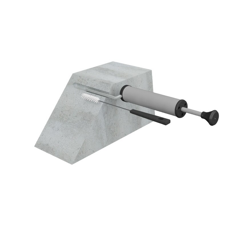
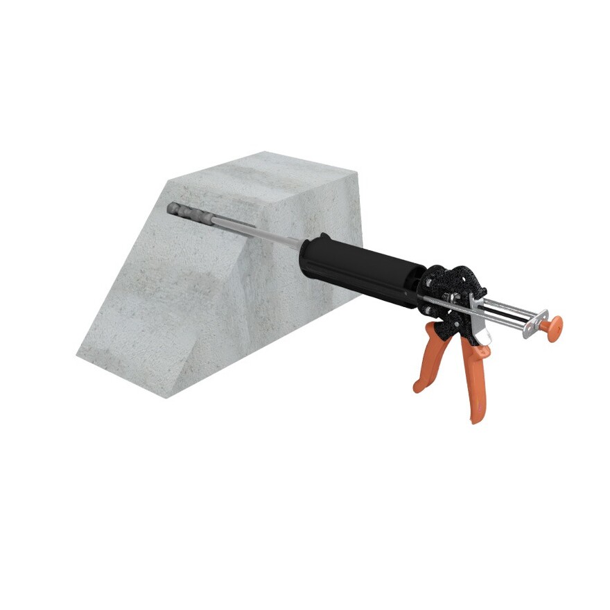
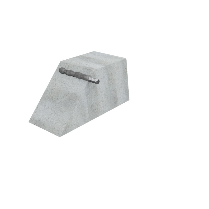
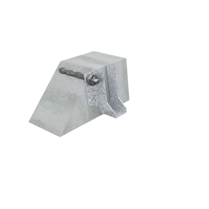
Asennus
Kovettuminen
Mortar temperature Tmortar [°C) | Base material temperature Tbase material [°C] | Gel time (working time) in dry/wet concrete tgel [min] | Curing time in dry/wet concrete tcure [h; min] |
| +5°C | -5°C to -1°C | 15min | 9h |
| +5°C | 0°C to 4°C | 12min | 4h |
| +5°C | 5°C to 9°C | 9min | 1,5h |
| +10°C | 10°C to 19°C | 4min | 60min |
| +20°C | 20°C to 29°C | 1min | 30min |
| +30°C | 30°C and above | <1min | 20min |
Concerning the version of the mortar with changing color proof, after the minimum curing time the blue colored injection mortar changed into grey. The curing color proof is available for standard version of the mortar only and the curing color proof is working above 5°C.
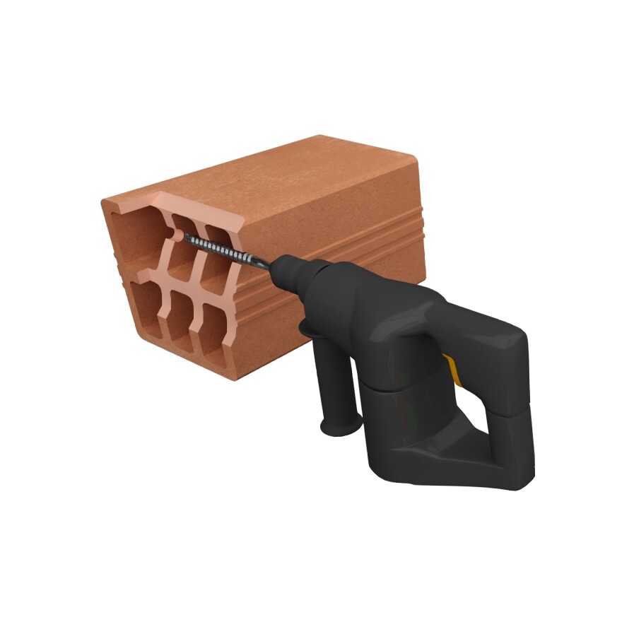
Drilling methods
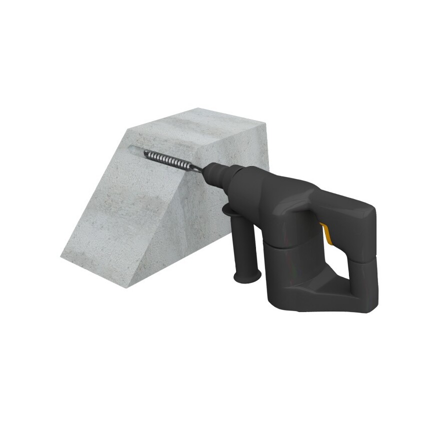
| Solid brick/concrete | Percussion/hammer drilling |
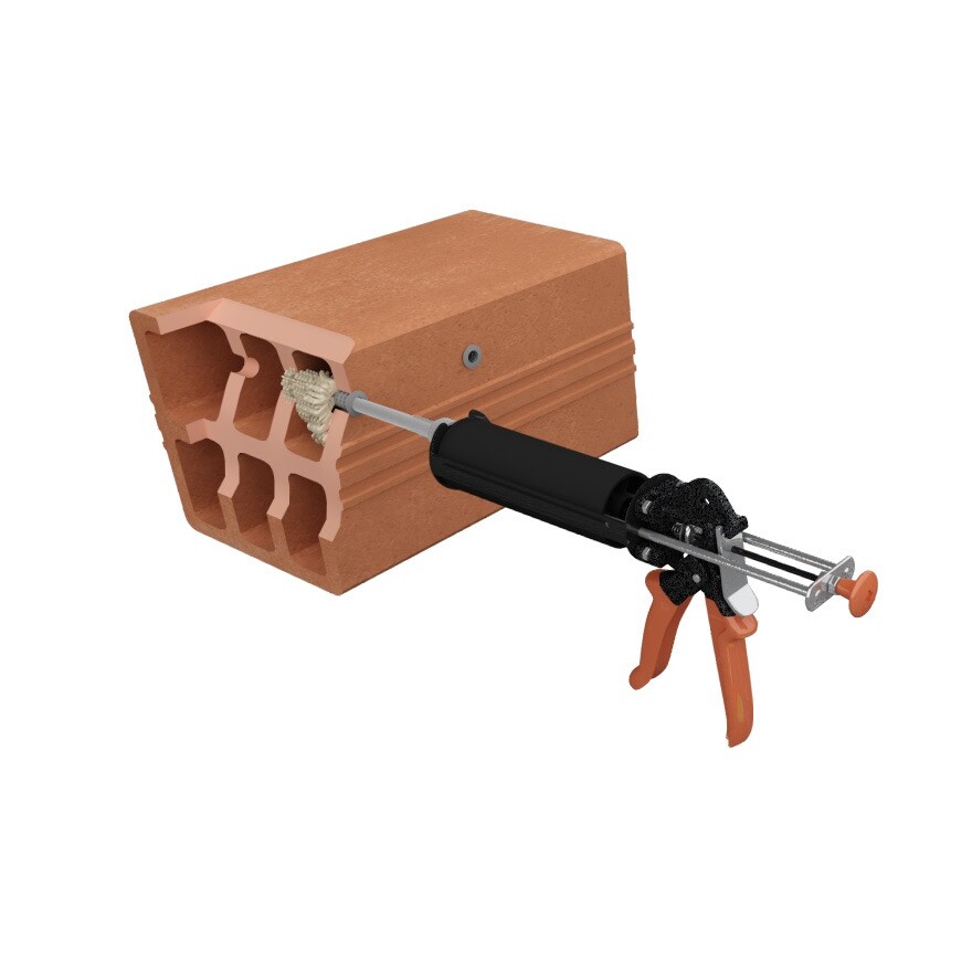
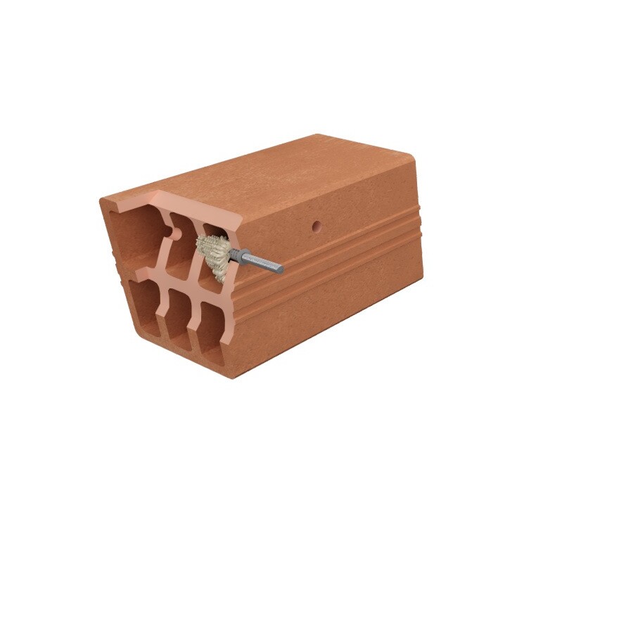
| Hollow/perforated brick | Rotation drilling |
| Aerated concrete | Percussion/hammer drilling |
Installation parameters – Concrete
| Tuotenro | Installation parameters - Concrete | |||||
|---|---|---|---|---|---|---|
| Ø drilling [d0] [mm] | Max. fixture hole Ø [df] [mm] | Drilling depth (8d) [h0=hef=8d] [mm] | Drilling depth (12d) [h0=hef=12d] [mm] | Wrench size [SW] | Installation torque [Tinst] [Nm] | |
| AT-HP + LMAS M8 | 10 | 9 | 64 | 96 | 13 | 10 |
| AT-HP + LMAS M10 | 12 | 12 | 80 | 120 | 17 | 20 |
| AT-HP + LMAS M12 | 14 | 14 | 96 | 144 | 19 | 30 |
| AT-HP + LMAS M16 | 18 | 18 | 128 | 192 | 24 | 60 |
| AT-HP + LMAS M20 | 24 | 22 | 160 | 240 | 30 | 90 |
| AT-HP + LMAS M24 | 28 | 26 | 192 | 288 | 36 | 140 |
Spacing, edge distances and member thickness - Concrete
| Tuotenro | Spacing, edge distance and member thickness - Concrete | |||||||||
|---|---|---|---|---|---|---|---|---|---|---|
| Effective embedment depth (8d) [hef,8d] [mm] | Characteristic spacing for hef,8d [Scr,N] [mm] | Characteristic edge distance for hef,8d [ccr,N] [mm] | Min. member thickness for hef,8d [hmin] [mm] | Effective embedment depth (12d) [hef,12d] [mm] | Characteristic spacing for hef,12d [Scr,N] [mm] | Characteristic edge distance for hef,12d [ccr,N] [mm] | Min. member thickness for hef,12d [hmin] [mm] | Min. spacing [Smin] [mm] | Min. edge distance [Cmin] [mm] | |
| AT-HP + LMAS M8 | 64 | 192 | 96 | 100 | 96 | 288 | 144 | 100 | 40 | 40 |
| AT-HP + LMAS M10 | 80 | 240 | 120 | 110 | 120 | 360 | 180 | 150 | 50 | 50 |
| AT-HP + LMAS M12 | 96 | 288 | 144 | 126 | 144 | 432 | 216 | 174 | 60 | 60 |
| AT-HP + LMAS M16 | 128 | 384 | 192 | 158 | 192 | 576 | 288 | 222 | 80 | 80 |
| AT-HP + LMAS M20 | 160 | 480 | 240 | 190 | 240 | 720 | 360 | 270 | 100 | 100 |
| AT-HP + LMAS M24 | 192 | 576 | 288 | 222 | 288 | 864 | 432 | 318 | 120 | 120 |
Installation parameters – Rebar
| Tuotenro | Installation parameters - Rebar | ||
|---|---|---|---|
| Ø drilling [d0] [mm] | Drilling depth (8d) [h0=hef=8d] [mm] | Drilling depth (12d) [h0=hef=12d] [mm] | |
| AT-HP + Ø8 | 12 | 64 | 96 |
| AT-HP + Ø10 | 14 | 80 | 120 |
| AT-HP + Ø12 | 16 | 96 | 144 |
| AT-HP + Ø14 | 18 | 112 | 168 |
| AT-HP + Ø16 | 20 | 128 | 192 |
| AT-HP + Ø20 | 25 | 160 | 240 |
| AT-HP + Ø25 | 32 | 200 | 300 |
Spacing, edge distances and member thickness – Rebar
| Tuotenro | Spacing, edge distance and member thickness - Rebar | |||||||||
|---|---|---|---|---|---|---|---|---|---|---|
| Effective embedment depth (8d) [hef,8d] [mm] | Characteristic spacing for hef,8d [Scr,N] [mm] | Characteristic edge distance for hef,8d [ccr,N] [mm] | Min. member thickness for hef,8d [hmin] [mm] | Effective embedment depth (12d) [hef,12d] [mm] | Characteristic spacing for hef,12d [Scr,N] [mm] | Characteristic edge distance for hef,12d [ccr,N] [mm] | Min. member thickness for hef,12d [hmin] [mm] | Min. spacing [Smin] [mm] | Min. edge distance [Cmin] [mm] | |
| AT-HP + Ø8 | 64 | 192 | 96 | 100 | 96 | 288 | 144 | 100 | 40 | 40 |
| AT-HP + Ø10 | 80 | 240 | 120 | 110 | 120 | 360 | 180 | 150 | 50 | 50 |
| AT-HP + Ø12 | 96 | 288 | 144 | 126 | 144 | 432 | 216 | 174 | 60 | 60 |
| AT-HP + Ø14 | 112 | 336 | 168 | 148 | 168 | 504 | 252 | 204 | 70 | 70 |
| AT-HP + Ø16 | 128 | 384 | 192 | 168 | 192 | 576 | 288 | 232 | 80 | 80 |
| AT-HP + Ø20 | 160 | 480 | 240 | 210 | 240 | 720 | 360 | 290 | 100 | 100 |
| AT-HP + Ø25 | 200 | 600 | 300 | 264 | 300 | 900 | 450 | 364 | 125 | 125 |
